
Carel Controller Wiring Diagram
Control can be set as on/off (proportional) or proportional, integral and The first relay output (refer to internal wiring diagram) of the controller must be a solid state relay (ssr) to tolerate the high number of cycles.
Carel Controller Wiring Diagram
Display and visualisation 8 3.3.

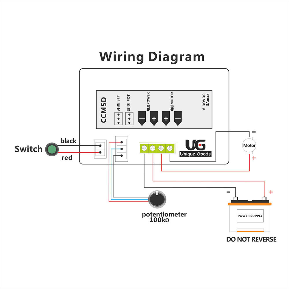
Carel controller wiring diagram. Bypass damper control and wiring is by others. The figure below shows the dimensions for each size. I have a heatcraft refrigeration unit with a carel controller pzhec0001k.
• place the controller on the din rail and press it down gently. This is a instructional video on how to program our carel pjez* easy digital controller · 1 large cord grip for retention of new flex.
Ir33+ platform ir33+, ir33+wide, ir33+ small wide which are required/indicated in the user manual, may cause the final product to malfunction. The controller fitted to the powerpax‐smardt water cooled chiller is a plc based device manufactured by carel utilizing imbedded control software written specifically by powerpax‐smardt forwerpaxpo ‐smardt chiller The tabs at the back will snap into place and lock the controller.
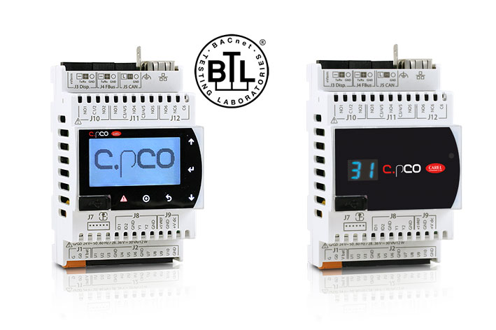
3 eng ir33plus +0300028en rel. Compared to pco sistema, the range is enhanced by a new compact controller, and consequently Kenworth t660 stereo speaker wiring diagram.
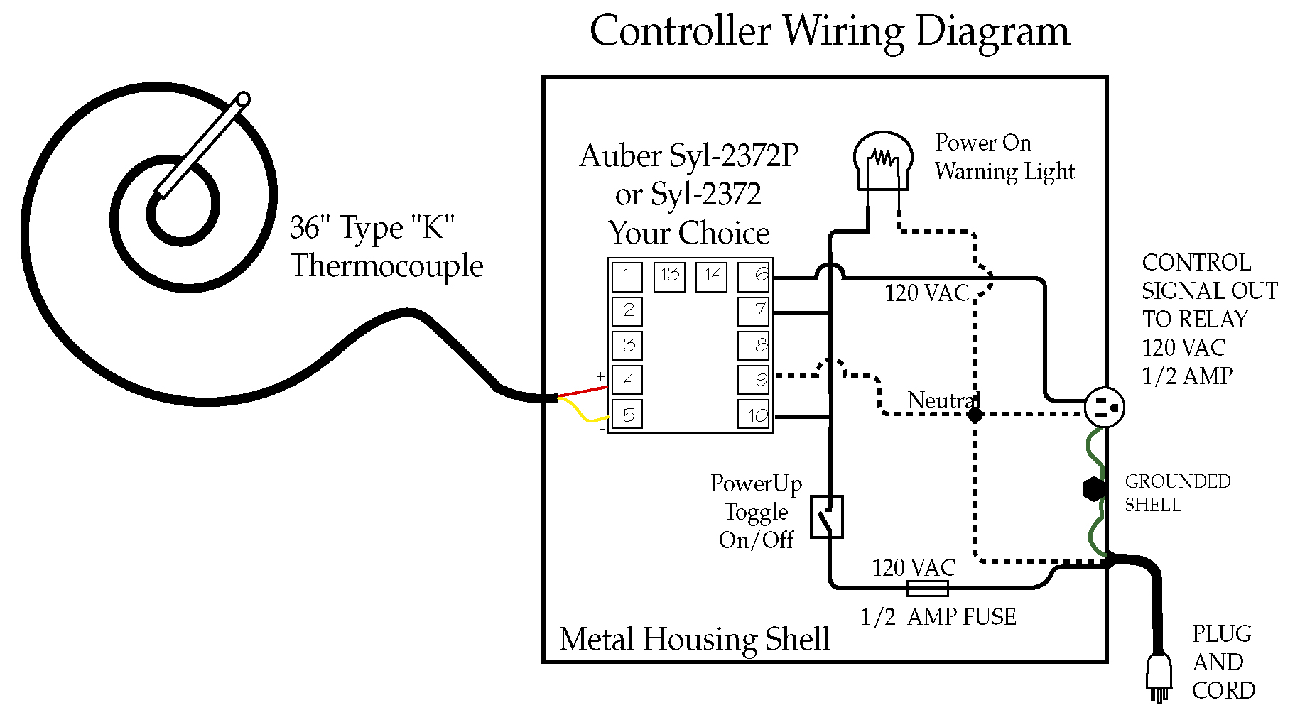
Carel description set point differentia neutral zone models msyfch syfch syfch def def. 1.1.1 main functions • control of. The operating manual shows the wiring diagram for a forced air heater.
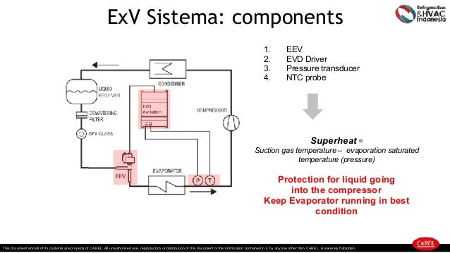
Skip to the beginning of the images gallery. Liebert challenger 3000 wiring diagram. Carel controller that controls the compressor and processes data from the evd controller.
The controller is designed to be mounted on a din rail. Connect the control wiring to the terminals on the unit as indicated in table 2.1. Identify the controller / thermometer.
If the distance between the pgd1 and the carel controller exceeds 100 feet, refer to the appropriate carel literature for further information. • lift the tabs using a screwdriver applied to their release slots. The ssr on the dcm control is pilot duty, and is used.
St 20 60 oc/of oc/of oc/of 16 34 16 34 r/vv minimum set oint maximum set oint operating mode 0 = direct with defrost control (cooling) 1 = direct (coo ing) 2 = reverse (heatin ) Exploiting the experience acquired over recent years, mastercella has been upgraded and proposed in a modern design, so as to better respond to customer expectations. • power supply, normally the same as the.
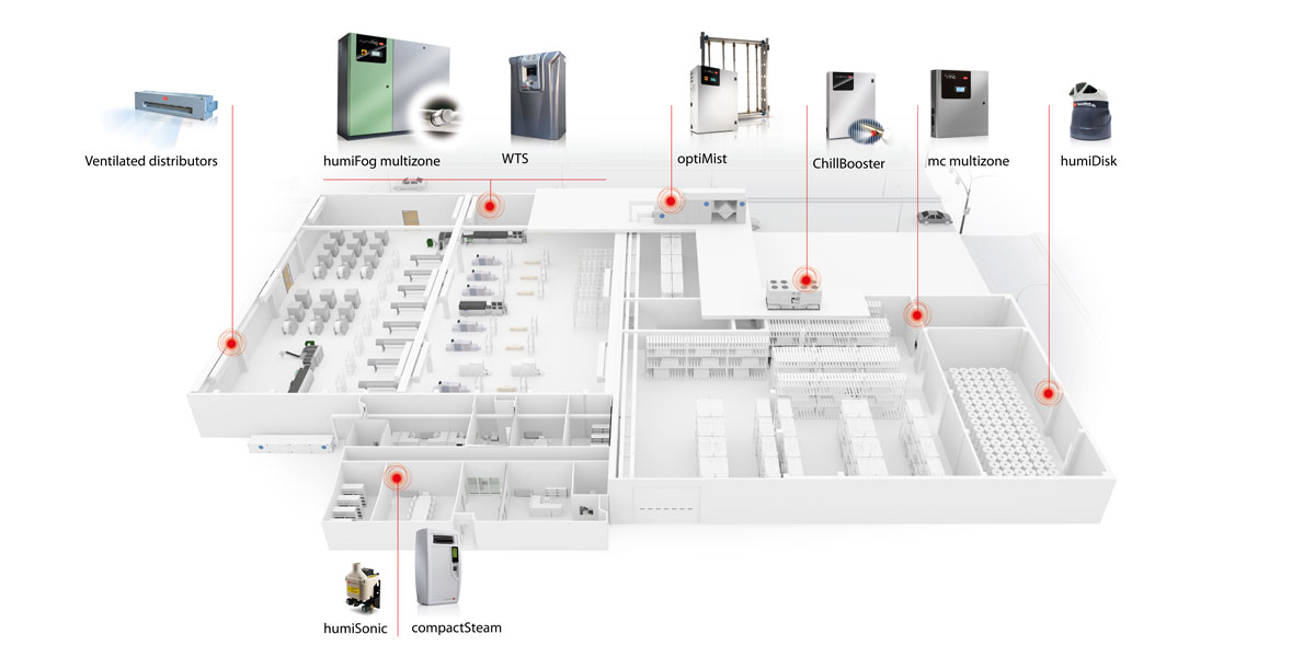
Case, combination with other carel controllers is recommended (supervisors and cold room controllers). Integrated control solutions & energy savings ir33+ platform ir33+, ir33+wide, ir33+ small wide. The new generation mastercella is the response to the need for integrated cold room.
Dimensions, weights, hose connections 2.1 positioning • to favour steam distribution, position the appliance so as to minimise the length of the steam outlet pipe (max 4 m). Connect the control wiring to the base terminals, running the wiring through the hole in the center of the base. Mastercella represents one of the leading products in the refrigeration range offered by carel.
For the connection at the unit mounted controller, refer to the section wiring connection at unit controller. Carel thermostat wiring diagrams standard installation installation with ssc (smart speed control) 12v installation for spillover fan carel 1 2 4 5 7 8 digital thermostat/thermometer 12v positive (+) 12v negative (‐) "c" terminal on controller fuse, 2 amp "t" terminal on controller • power supply, normally the same as the.
Carel bases the development of its products on decades of experience. To silence alarm press ". Can seem to understand the program set up and my condenser fans will not turn on.
We are installing a honeywell r8285a,b control center to a hot water boiler. The sensors can have an alternating current (12 to 24 vac) or direct current (9 to 30 vdc) power supply. Attach the pgd1 controller to the back that was mounted
The µc2 is a new compact carel electronic controller, the same size as a normal thermostat, for the complete management of chillers and heat pumps: Sr8cs10dc48sr stetron relay wiring diagram. Skip to the end of the images gallery.
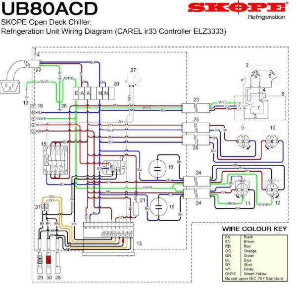
Sl refrigeration unit (skope carel ir33 controller). Trane air handler model bwh718a100a1 wiring diagram. Its fl exibility allows for creation of tailor made control solutions according to customer specifi cations.
· the programmed carel skope ir33 electronic controller · copy of this service bulletin including wiring diagrams (prn2997) · replacement controller flex and 3 new controller probes.
[DIAGRAM in Pictures Database] Ps2 Slim Schematic Wiring Just Download or Read Schematic Wiring

Ncs Alarm Wiring Diagram HOPESYOUNGADULTCHALLENGE

Carel Ir33 Wiring Diagram
Carel Controller Wiring Diagram

Carel Ir33 Wiring Diagram

Carel Pressure Transducer Wiring Diagram / Innovative Cold Room Solutions Efficiency Reliability

BMS Programmers small but efficient controller c.pCO Carel YouTube
Carel Ir33 Wiring Diagram
Chiller Control Wiring Diagram 39
Carel Pressure Transducer Wiring Diagram / Innovative Cold Room Solutions Efficiency Reliability

Carel Pressure Transducer Wiring Diagram / Innovative Cold Room Solutions Efficiency Reliability

Carel Ir33 Wiring Diagram
Carel Ir33 Wiring Diagram
Looking for a wiring diagram for Corel IR32C0LBR0 can you help
Carel Ir33 Wiring Diagram
Carel Controller Wiring Diagram


Carel Ir33 Wiring Diagram

Pegasus 21 CAREL ir33 Controller Changeover

Carel Ir33 Wiring Diagram
